
ZCW□-72.5
This product is developed in accordance with IEC international standards, featuring reasonable structure, reliable performance, strong breaking capacity and high operation stability. It is mainly used for switching, control and protection of power lines and equipment in power substations, industrial power systems and urban power grids.
With excellent outdoor environmental adaptability, ZCW□-72.5 can operate stably in harsh conditions such as high altitude, low temperature, heavy pollution and coastal areas. It has the advantages of small installation space, convenient maintenance, long service life and high safety, making it an ideal equipment for modern power construction and transformation projects.
Product Details
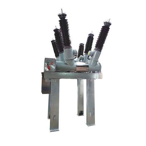
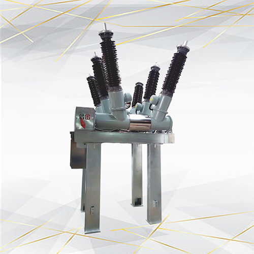
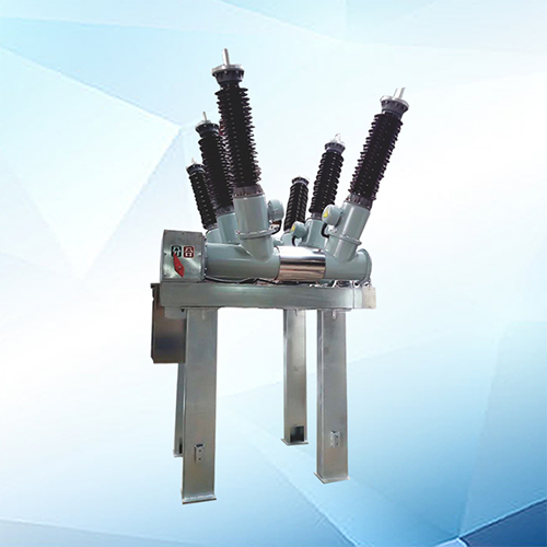
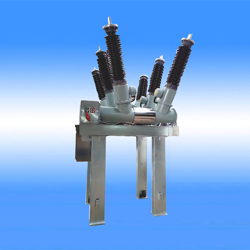
ZCW□-72.5(126.5)/L
Open air type assembled switch gear
□Meaning of type

□Introduction
□ZCW□-72.5(126.5)/L- type open-type combination of electrical appliances is the use of air as the outer insulation SF6 gas as the interrupter medium complete sets of electrical appliances.For three-phase AC72.5KV power transmission and distribution system control and protection can also be used to contact the circuit breaker and opening and closing capacitor group of occasions.Suitable for land tension city substation,enterprise substation, mountain substation.□ Characteristic of structure
□The circuit breakers,disconnectors,grounding switches,current transformers,bus and other components of the organic combination of grounded steel structure bracket,compact structure.
□Il ts share of space only split 30%-50%,with land savings,reduce construction costs and other notable features.
□The entire interval factory prefabricated,completed the assembly and all the debugging before shipment and shipped to the installation site,greatly reducing the installation cycle.
□The use of fully proven high-performance interrupters,disconnectors,basic maintenance-free,high reliability.
□I nter-bay factory prefabricated self-supporting bus,without the need to build the framework.
□ Flexible layout,can be used for a variety of wiring.
□Circuit breakers can be reduced overhaul or repplacement as a whole,due to body failure power outage time can be reduced to at least 3 hours.
□Technical data
1)Main technical data of breaker
|
No. |
N a m e |
Unit |
Value |
||
|
1 |
Rated voltage |
|
72.5 |
||
|
2 |
Rated power frequency withstand voltage(1min) |
To earth |
kV |
K ·160 |
|
|
Between interrupter |
K ·200 |
||||
|
3 |
Rated thunder impulse withstand voltage |
To earth |
K ·350 |
||
|
Between interrupter |
K ·410 |
||||
|
4 |
Power frequency withstand voltage under zero gauge pressure ofSF6(5 min) |
K ·84 |
|||
|
5 |
Rated frequency |
Hz |
50 |
||
|
6 |
Rated current |
A |
3150 |
||
|
7 |
Amplitude factor |
|
1.5 |
||
|
8 |
Rated short-circuit breaking current |
|
31.5 |
||
|
9 |
Rated short-circuit making current(peak) |
kA |
80 |
||
|
10 |
Rated short-circuit with stand current |
31.5 |
|||
|
11 |
Rated peak value withstand current |
80 |
|||
|
12 |
Rated short-circuit duration |
s |
4 |
||
|
13 |
ated out-of-phase breaking current |
kA |
8 |
||
|
14 |
Breaking current of close-in fault |
kA |
90%lk,75%lk |
||
|
15 |
Rated line-charging breaking current |
A |
10 |
||
|
16 |
Operating sequence |
|
O-0.3s-CO-180s-CO |
||
|
17 |
Resistance of the main circuit |
μΩ |
≤40 |
||
|
18 |
Rated gauge pressure of SF6(20℃) |
Mpa |
0.5 |
||
|
19 |
Minimum functional gauge pressure(20℃) |
Mpa |
0.45±0.03 |
||
|
20 |
Annual leakage rate of SF6 |
|
<0.5% |
||
|
21 |
Amount of water of SF6(V/V) |
|
≤150×10-8 |
||
|
22 |
Mechanical life |
Times |
10000 |
||
|
23 |
Electricallevel of radio interference |
μV |
≤500 |
||
|
24 |
Creepage distance |
Between interrupter |
mm |
2585 |
|
|
To earth |
2248 |
||||
|
25 |
Each filled with SF6 gas weight |
kg |
10 |
||
|
26 |
Weight per breaker |
kg |
1300 |
||
Note:external insulation level is changed by modified coefficient.Every 2000m of altiude,K=1.13:Altitude 3000m,K=1.28.
2)Main technical data of structure
|
No. |
N a m e |
Unit |
Value |
|
|
1 |
Auxiliary circuit voltage |
V |
DC220 or DC110 |
|
|
2 |
The voltage/current of the opening and closing coils |
V/A |
DC110/4;DC220/2 |
|
|
3 |
Energy storage motor |
Rated voltage |
V |
DC220、AC220/DC110、AC110 |
|
|
|
The range of normal working voltage |
V |
85%~110% |
|
|
|
Power |
W |
600 |
|
4 |
The energy storage time of motor |
s |
≤15 |
|
|
5 |
The loop voltage of the heater and the lamp |
V |
AC220 |
|
|
6 |
Rated voltage of the auxiliary switch |
V |
DC220、AC220 |
|
|
7 |
Rated current of the auxiliary switch |
A |
10 |
|
|
8 |
Contacts of the auxiliary switches |
|
10 normal opened contacts and 10 normal closed contacts |
|
3)Mechnical adjustment of the breaker
|
No. |
N a m e |
Unit |
Value |
|
1 |
Center distance between poles |
mm |
1200 |
|
2 |
Strode length of the moving contact |
mm |
120+3 |
|
3 |
Contact stroke length of the moving contact |
mm |
25+2 |
|
4 |
Length of the inter phase operating connecting rod |
mm |
110+3 |
|
5 |
Switch-off speed |
m/s |
4.2-5m/s |
|
6 |
Switch-on speed |
m/s |
2.2-3m/s |
|
7 |
Switch-of ime |
ms |
≤40 |
|
8 |
Switch-on time |
ms |
≤100 |
|
9 |
Break time |
ms |
≤60 |
|
10 |
Switch-on/off time |
ms |
≤80 |
|
11 |
Switch-off/on time |
ms |
300 |
|
12 |
The time difference of the opening of three phases |
ms ms- |
≤2 |
|
13 |
The time difference of the closing of three phases |
|
≤3 |
□Order notice
□The type and the specification of the circuit breaker.
□ Rated electric parameter(voltage,current,rated short-circuit breaking current and so on).
□Rated electric parameter of control loop(rated voltage of energy storage motor,rated voltage o fthe opening and closing coils).
□The name and the number of the accessories when required.
□ The connection direction of the primary upper terminal.
□Outline dimension
□As per the drawing below.
□ZCW □-72.5(126.5)/L-type open type combined electrical weight:1500kg.
□Front face area:4.5m²

Online Inquiry
Or use the inquiry form below. Our sales staff will contact you within 24 hours. Thank you for your interest in our products!